


 21 / 82

A D V A N C E D
M A T E R I A L S
&
P R O C E S S E S | F E B R U A R Y / M A R C H
2 0 1 7
2 1
M
easurement of grain size and
distribution can be performed
using bothmanual (ASTM E112)
and image analysis (E1382) methods.
Standard E112 is designed to measure
grain size in specimens with equiaxed
grains and a unimodal (normal), or
Gaussian, grain size distribution. How-
ever, it does not define how to deter-
mine if grains in a specimen adhere to
this criterion. This article demonstrates
how to evaluate grain size distribution,
which can be done using either grain-
area or intercept-lengthmeasurements.
The use of grain areas to evaluate distri-
bution is preferred, as the amount of
data per field is less, and the calculation
of ASTM grain size, G, is a simple and
direct matter. Further, the relationship
between mean lineal intercept length
and grain size is empirical.
Grain structures of some metal
specimens have grain distributions
other than unimodal or Gaussian dis-
tribution. For example, high-alloy and
stainless steels and nickel-base superal-
loys commonly have bimodal grain size
distributions in the as-rolled and solu-
tion annealed condition—especially if
the annealing temperature is below the
recommended temperature. A range of
distributions can exist between speci-
mens that exhibit unimodal Gaussian
distributions and those that clearly ex-
hibit bimodal, or duplex, grain size dis-
tributions. Because the nature of grain
size distribution can influence mechan-
ical properties and service behavior, it
is important to accurately characterize
this parameter. The best way to evalu-
ate grain size distribution is to measure
grain areas and plot the percentage of
grain areas per ASTM G class versus
ASTM grain size number (G), while cal-
culating the skew and kurtosis (sharp-
ness of the peak of a frequency-distri-
bution curve) of the measured grain
areas. A kurtosis of 3 represents a per-
fect unimodal, or Gaussian, grain size
distribution, while values of >5 indicate
non-Gaussian distributions.
ANALYTICAL PROCEDURE
Grain areas can be measured using
image analysis (IA) and electron back-
scatter diffraction (EBSD). A reasonably
large number of grains (typically, at least
500 grains) must be measured using
randomly selected fields; both methods
required excellent metallographic spec-
imen preparation. For IA, grain structure
must be fully revealed with minimal
missing grain edges between adjacent
grains, although this technique can
correct for some missing grain bound-
aries. EBSD requires a specimen with
excellent flatness and freedom from de-
formation-induced subsurface damage,
which reduces the percentage of pixels
that generate diffraction patterns that
can be indexed. If a face-centered-cu-
bic metal specimen exhibits annealing
twins, they must be suppressed by the
etchant used, removed by the image
analysis program, or removed by the
orientation differences across the twin
boundary by EBSD.
To define a normal distribution,
plot the area percentage of grains per
ASTM grain size class. The definition of
G according to E112 is:
N
AE
= 2
G-1
(1)
where N
AE
is the number of grains per
square inch at a magnification of 100×
and G is the ASTM grain size number.
Skew and kurtosis are calculated from
ANALYSIS OF GRAINSIZE
DISTRIBUTIONS
Because the nature of grain size distribution can influence mechanical properties and
service behavior, it is important to accurately characterize this parameter.
George F. Vander Voort, FASM,* Struers Inc. (Consultant), Cleveland
the raw measurement data of the grain
areas. Calculate the kurtosis of the data
using an application such as Microsoft
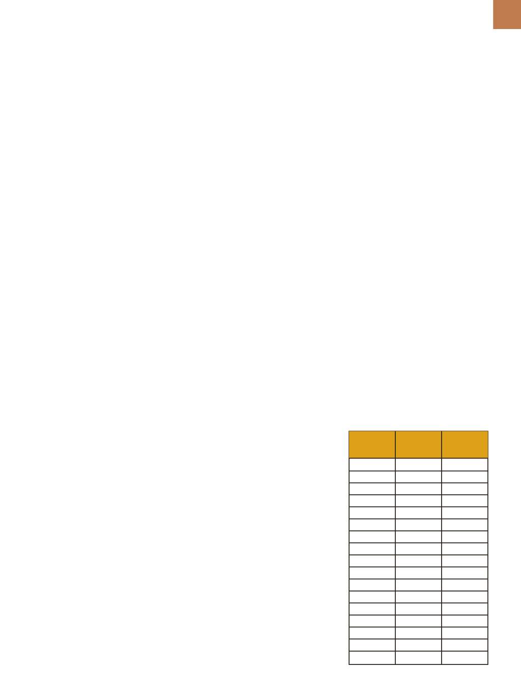
Excel. Next, order grain areas from larg-
est to smallest, then add up grain areas
according to how they relate to specific
ASTM G values as shown in Table 1. In
the table, for a given G class, areas are
binned according to the area for a given
G value plus or minus the area for G-0.5
to G+0.5. Total grain areas for each G
value are summed and divided by the
total areas of all measured grains and
expressed as a percentage.
ANALYSIS EXAMPLES
Example 1.
Figure 1 shows the
microstructure of a motor lamination
steel with a very low carbon content,
ASTM G A max,
A min,
μ
m
2
μ
m
2
TABLE 1—BINNING OF GRAIN AREAS
BY ASTM G CLASS
00
365,008
182,504
0
182,504
91,239
1
91,239
45,620
2
45,620
22,810
3
22,810
11,405
4
11,405
5703
5
5703
2851
6
2851
1426
7
1426
713
8
713
356
9
356
178
10
178
89.5
11
89.5
44.6
12
44.6
22.3
13
22.3
11.1
14
11.1
5.57
15
5.57
2.79
*Member of ASM International