


 64 / 82

A D V A N C E D M A T E R I A L S & P R O C E S S E S | F E B R U A R Y / M A R C H 2 0 1 7
6 4
FEATURE
14
of 27 kW, is capable of heating the coupon surface to 1600°F,
achieving a maximum surface heat flux of 10.8 MW/m
2
.
Data collection begins when the coupon is at its max-
imum temperature and stable film boiling is established at
the desired quenchant flow rate and temperature. Collec-
tion continues as the heaters reduce the surface tempera-
ture of the coupon at a controlled rate of 20°F/minute. This
slow cooling approach provides a well-defined relation-
ship between surface temperature and surface heat flux
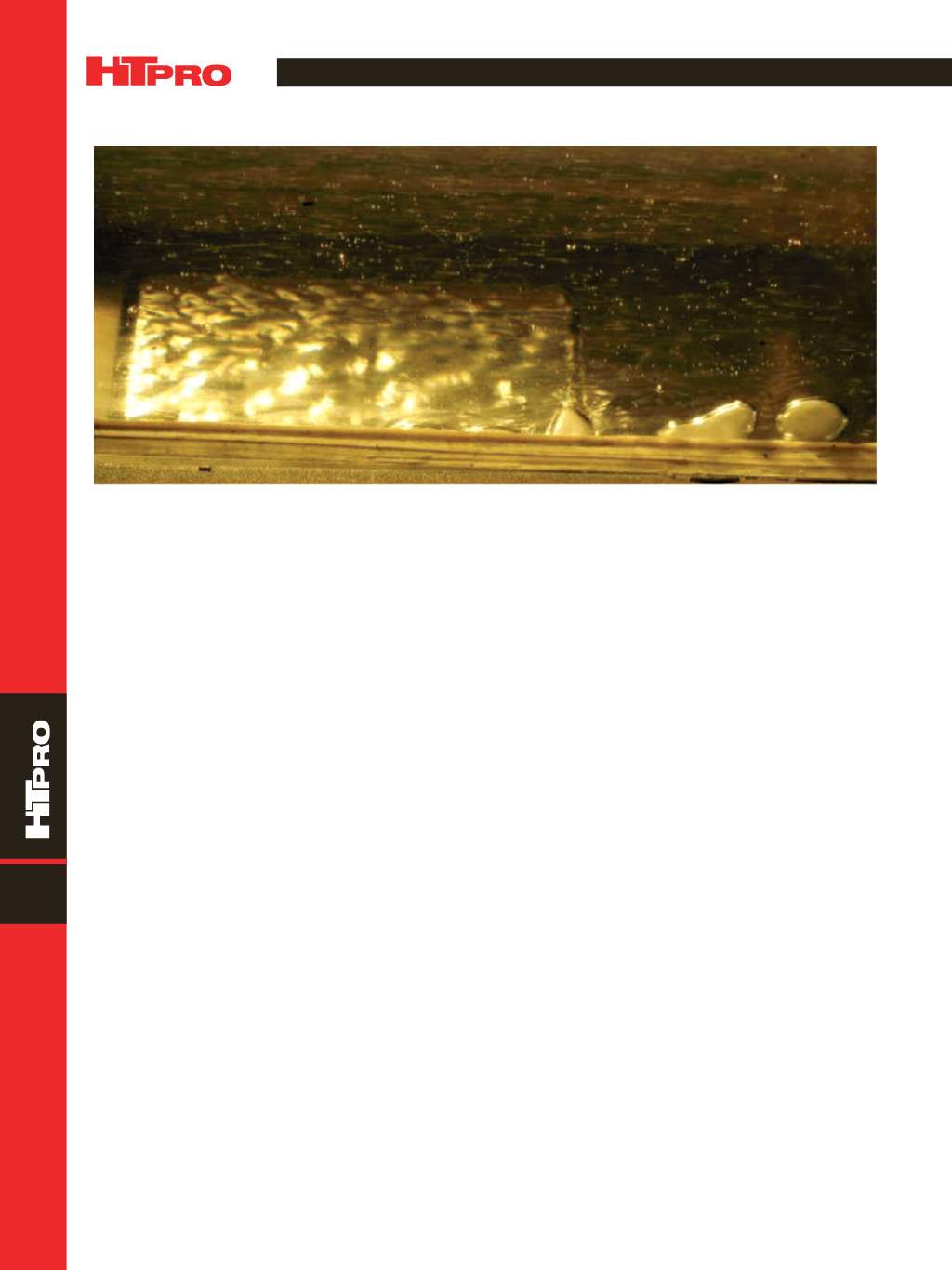
during pseudo-steady-state conditions. Figure 2 shows the
vapor-liquid interface on the test coupon during film boil-
ing at a relatively low flow rate. The test procedure is then
repeated for each flow velocity, quenchant temperature,
and surface orientation of interest.
The raw data collected are temperature values ob-
tained from thermocouples inserted below the surface of
the copper coupon. The values are used to derive surface
temperature and heat flux rate. The procedure may seem
similar to the inversing processes typically used in quench
trials, although there are a few key differences. First, all data
are collected in near steady-state conditions, eliminating the
complexities inherent in transient cooling processes. Sec-
ond, two thermocouples are used at each surface location,
placed at different depths, allowing for advanced extrapola-
tion techniques to the surface of the coupon
[1]
. And finally,
because surface heat flux data are linked to surface tem-
perature, quenchant temperature, quenchant velocity, and
surface orientation, they can be applied to any surface under
the same conditions.
QUENCH TESTING, SIMULATION
AND VALIDATION
To validate themethod, quenching datawere collected
on a generic turbine disk shape made of Inconel 718. Nearly
two dozen thermocouples were inserted into the part at crit-
ical locations. Most of the thermocouples were placed 0.100
in. from the surface, while five were buried deeper into the
part. Near the rim of the disk, the near-surface thermocou-
ple was repeated at 60° intervals to assess the circumferen-
tial uniformity of the quenching operation.
In quench tests performed at the Wyman-Gordon
research facility in Houston, the disk was soaked at 1800°F,
then quenched in Houghton 3420 quenchant under both
still and agitated conditions. Temperature data were col-
lected at 10 Hz during both the heating and quenching
cycles.
The quenching operation was simulated with
ANSYS-Fluent version 16, using a 0.1 second time step. For
the still oil quenching simulation, radial symmetry of the
part allowed for a 2D model, and 17,557 cells were used to
represent both the disk and quench tank in cross section.
Simulating a quench of 1500 seconds required about five
hours of processing time on a 3.5-GHz Linux workstation
with eight processors.
Boiling functions constructed from the flow boiling
database were incorporated into a Fluent User Defined
Function (UDF) that adjusted the surface heat transfer
coefficients (HTCs) on an iterative basis for each surface
Fig. 2 —
Filmboiling on side surface at low velocity and high temperature. Flow is from left to right. Vapor film is thick and uneven, and
vapor bubbles are being shed.